|
ELECTRICAL PROPERTIES OF PLASTICS
Commercial plastics are generally very good electrical insulators
and offer freedom of design in electrical products. Electrical properties may
also be changed by environmental conditions, such as moisture and/or
temperature.
A BASIC CONCEPT TO REMEMBER is that electrons must be
exchanged between molecules for electric current to flow through a material.
Plastic molecules hold on to their electrons and do not permit the electrons to
flow easily; thus plastics are insulators.
The molecules in plastics are also "polar" which means that
they will tend to act like little magnets and align themselves in the presence
of a voltage or field, the same as the needle in a compass trying to point
North.
The electrical properties of plastics are usually described
by the following properties:
VOLUME RESISTIVITY
The Volume Resistivity is defined as the ratio between the voltage (Direct
Current or DC), which is like the voltage supplied by a battery, and that
portion of current which flows through a specific volume of the specimen. Units
are generally ohm per cubic centimeter.
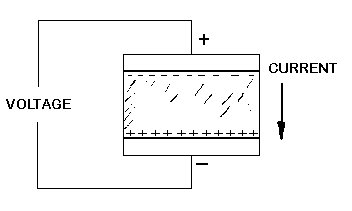
Visualize putting DC electrodes on opposite faces of a one
centimeter (.394 inch) cube of a plastic material. When a voltage is applied,
some current will flow in time as the molecules align themselves (Figure 30).

Figure 30
Ohm's Law tells us that a voltage (volts) divided by the
current (amps) is equal to a resistance (ohms) or V/I = R. When the voltage
applied to the cube is divided by the current, the resistance for 1 cm of the
plastic is determined or ohm per cm.
Generally plastics are naturally good insulators and have
very high resistance. The Volume Resistivity can change with temperature and the
presence of moisture or humidity.
SURFACE RESISTIVITY
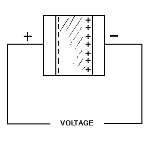
The Surface Resistivity is the ratio between the direct voltage (DC) and
current along the surface per unit width. Units are generally ohms.
Again refering to Ohm's Law, The Surface Resistivity is a
measure of how much the surface of the material resists the flow of current.

Figure 31
DIELECTRIC CONSTANT
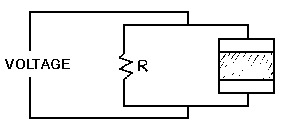
The Dielectric Constant is the ratio of the capacitance (AC voltage) of
electrodes with the insulating material between them to the capacitance of the
same electrodes with a vacuum or dry air in between.
The dielectric constant is a measure of how good a material
works to separate the plates in a capacitor. Remember that the molecules are
like little magnets and are trying to realign themselves every time the voltage
(current) changes direction. Some materials do it better than others.
The dielectric constant for a vacuum has a value of 1. Dry
air is very nearly 1. All other materials have "dielectric constants" that are
greater than 1. The "dielectric constant" for a plastic material can vary with
the presence of moisture, temperature, and the frequency of the alternating
current (and voltage) across the plates.
The units for frequency are usually "HERTZ (Hz)" which
means cycles per second. 3 kilohertz is the same as 3,000 hz and 3 megahertz is
the same as 3,000,000 hz.
DIELECTRIC STRENGTH
Dielectric Strength is the voltage difference (DC) between two electrodes
at which electrical breakdown occurs and is measured as volts per mil of
thickness. This is an indication of how effective an "insulator" the material
is.
Note: One mil is another way of saying .001 of an inch, so a
piece of plastic film 5 mils thick is .005 inch thick.
The test is similar to that used for "Volume Resistivity"
except the voltage is increased until there is an are across the plates. This
means that the voltage was strong enough to break down the material and allow a
large current to flow through it. Again this property can be affected by the
presence of moisture and temperature. Frequency may also affect this property
when the material is subjected to an Alternating Current. See Figure 30.

Figure 32
DISSIPATION FACTOR
The Dissipation Factor (AC) is the tangent of the loss angle of the insulating
material. It can also be described as the ratio of the true in-phase power to
the reactive power, measured with voltage and current 90 degrees out of phase.
This is an indication of the energy lost within the
material trying to realign the molecules every time the current (voltage)
changes direction in alternating current. The property varies with moisture,
temperature, and frequency.

Figure 34
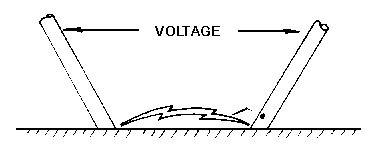
ARC RESISTANCE
The Arc Resistance is the elapsed time in which the surface of the
material will resist the formation of a continuous conductive path when
subjected to a high-voltage (DC), low-current arc under rigidly controlled
conditions.

Figure 35
EMI/RFI
There is also considerable effort being expended by material suppliers to
try and improve the conductivity of plastics for applications requiring EMI
(electromagnetic interference) and RFI (radio frequency interference) shielding.
This becomes more and more critical as circuitry is getting smaller and denser.
The improvement in conductivity is currently achieved by adding carbon fibers,
metal fiber, and/or metal flakes as a filler in the material or coating the
plastic part with conductive paint.
EMI and RFI are electromagnetic energy that can be emitted
by an electronic product and affect the operation of other electronic equipment
near it. Conversely, energy from the other products could interfere with the
operation of a given product. FCC regulations control the amount of energy that
can be emitted by a product.
Examples of EMI and RFI interference are: when you hear
other noise and/or stations on your car radio; when a CB broadcast is heard on
your FM receiver; when you see snow on your TV set when an appliance is run;
warnings in restaurants that a microwave is being used.
The screen or perforated metal seen in your microwave door
is an example of EMI/RFI shielding. Coaxial cable for your TV antenna is a wire
surrounded by a woven metal shield that is to be grounded. The shield absorbs
energy coming in from outside sources and keeps the signal in the wire pure
while preventing that signal from escaping and interfering with some other
electronic product.
Another serious potential problem is the static charge that
can be picked up walking across a room and zap an electronic product. The charge
can often be harmlessly dissipated by correctly grounding the equipment. The
application of an anti-static may also be used to provide a temporary solution.
| 

 Knowledge Base


 Knowledge Base


 Knowledge Base


